




UV Laser Marking on PTFE and ETFE Wire Insulation
Wire identification matters in aerospace harnesses, defense electronics, and electrical assemblies. Technicians need readable conductor numbers during installation, inspection, and maintenance, even in crowded bundles. The insulation surrounding each conductor determines whether an identification method can produce consistent results.
Polytetrafluoroethylene (PTFE) and ethylene tetrafluoroethylene (ETFE) share fluoropolymer chemistry but differ in mechanical behavior and insulation construction. UV laser marking offers a noncontact identification process for qualified, laser-markable formulations on PTFE and ETFE wire insulation. Understanding those distinctions helps manufacturers select equipment and evaluate quality.
How PTFE and ETFE Insulation Differ
Both materials provide chemical resistance and electrical insulation, yet manufacturers use them in different conditions. Material selection affects wire flexibility, abrasion resistance, temperature capability, and the markings manufacturers can achieve.
PTFE Wire Insulation
PTFE withstands high temperatures and exposure to many industrial chemicals. Aerospace manufacturers use PTFE-insulated conductors where electrical reliability and thermal performance matter. Its low surface energy also makes conventional ink adhesion challenging, creating an advantage for identification methods that do not rely on ink.
However, PTFE chemistry alone does not guarantee successful UV laser marking. Pigments, additives, and insulation-layer construction influence the material’s response to ultraviolet energy. A marking procedure for one PTFE product may not suit another manufacturer’s wire.
ETFE and Cross-Linked ETFE
ETFE provides greater mechanical toughness and abrasion resistance than PTFE in many constructions. Its properties support thin-wall insulation in aerospace wiring, where limited harness space makes outer diameter important. Cross-linked ETFE, or XL-ETFE, appears in specialized aerospace wire specifications.
Different ETFE formulations can produce different mark contrast. Colorants and processing history may affect appearance, so teams should assess the wire part number rather than treat all ETFE insulation as interchangeable.
What UV Laser Marking Does to the Insulation
UV laser marking on PTFE and ETFE wire insulation directs controlled ultraviolet energy onto the outer insulation surface. Compatible formulations respond with a visible color change, creating letters or numbers without ink deposition or physical contact. Manufacturers must qualify that response for the specific wire construction and performance requirements.
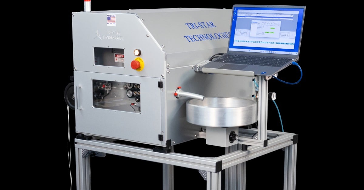
A laser marking machine manufacturer such as Tri-Star Technologies controls character formation through scanning patterns, marking-point density, and positioning. These details become critical when narrow conductors leave little room for human-readable identification.
PTFE Marking Considerations
PTFE’s marking response depends on the insulation formulation, not simply its polymer name. Two white PTFE-insulated wires may differ in contrast because their compositions or constructions differ. Testing the production wire helps manufacturers establish an acceptable identification process before releasing a batch.
ETFE Marking Considerations
ETFE and XL-ETFE also require construction-specific evaluation. Thin insulation walls demand careful process validation because identification cannot come at the expense of electrical or mechanical performance. Manufacturers should inspect both character visibility and the wire’s continued compliance with its applicable specification.
Aerospace Standards That Matter
Aerospace programs use defined marking procedures and legibility criteria rather than subjective visual judgments. Standards depend on wire construction and customer requirements.
SAE AS5649B: UV Laser Marking Process
SAE AS5649B, revised in May 2025, specifies process requirements for ultraviolet laser identification of aerospace wires and cables. Its scope connects qualifying laser-markable wiring under SAE AS4373 with the wiring requirements of SAE AS50881. It does not mean every PTFE or ETFE product automatically qualifies for laser marking.
For manufacturing teams, the practical distinction is important: qualification applies to the relevant wire construction and process. They should confirm the correct wire specification before selecting marking settings or releasing production.
SAE ARP5607B: Human-Readable Legibility
SAE ARP5607B provides guidance on the legibility of human-readable characters on wire and cable insulation. It addresses marking characteristics and viewing conditions, including lighting, viewing distance, and orientation. It does not establish criteria for barcodes or other machine-readable symbols.
Small-gauge wire presents a clear challenge: tight character spacing can make an eight resemble a B or cause neighboring numbers to merge visually. Manufacturers must examine the complete identifier during inspection, not just whether the laser produces a visible change.
SAE AIR5558A: Wire Construction Performance
SAE AIR5558A discusses UV laser mark contrast measurements across aerospace wire constructions. It provides informational guidance, rather than replacing the process requirements in AS5649B. The distinction reinforces why one successful sample cannot establish compatibility across an entire fluoropolymer family.
Defects That Compromise PTFE and ETFE Identification
Production teams should look for specific marking failures rather than use a single general pass-or-fail judgment. Each defect may point toward a different source of variation.
Weak or Uneven Contrast
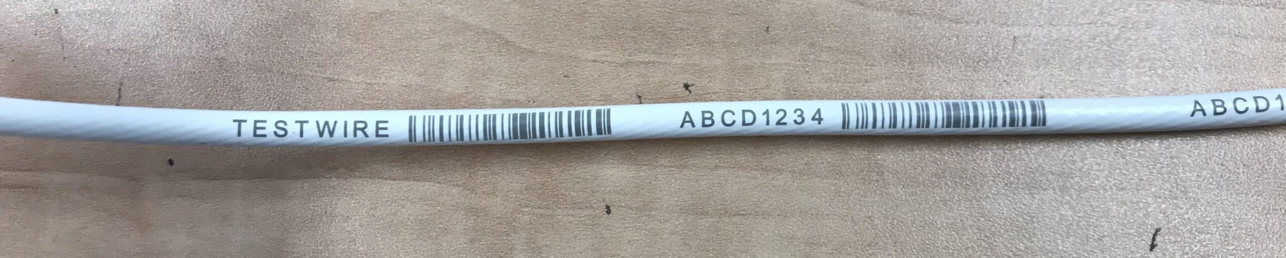
Faint identifiers can result from inadequate material responsiveness or inconsistent marking conditions. Changes between insulation batches may also affect appearance. Inspectors should compare marks against the criteria for that wire rather than assume every white jacket produces identical darkness.
Broken or Crowded Characters
Scanned UV marking constructs characters from closely positioned marking points. Excessive spacing can leave visible gaps in strokes, while insufficient character separation makes letters difficult to distinguish. Adjusting an approved pattern requires attention to legibility and production throughput together.
Stretched Characters During Wire Movement
Continuous processing adds a motion-control challenge. When the marking pattern does not synchronize with wire travel, characters may stretch, compress, or shift. Encoder-based coordination helps the equipment track line speed during spool-to-spool processing or extrusion-line integration.
Marks in the Wrong Position
Harness assembly instructions may require identification at specific intervals or distances from wire ends. A readable mark still fails its purpose when a connector boot, sleeve, or termination hides it. Accurate feeding and programmable placement help maintain location requirements.
Matching Equipment to the Production Workflow
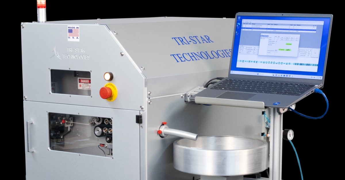
Standalone marking and continuous production require different approaches to handling wire. Tri-Star Technologies offers equipment specifically for these distinct integration points.
Standalone Marking and Wire Preparation
Tri-Star’s M100LFGTTA family supports programmed wire identification with controlled feeding and cutting. This approach suits manufacturers preparing individual conductors for harness assembly. Operators can coordinate identification content and cut lengths within a repeatable workflow, subject to the system’s configuration and qualified material compatibility.
Integrated and Continuous Marking
The M100LFGTTA-METEOR supports integration into continuous processes, including extrusion and spool-to-spool applications. Encoder synchronization helps maintain character geometry as speed changes. Tri-Star also offers an M100LFGTTA-S configuration for integration with compatible Schleuniger cut-and-strip equipment.
Equipment selection should account for the wire’s gauge, insulation specification, production speed, and marking intervals. A suitable mechanical layout cannot replace qualification of the intended PTFE or ETFE construction.
Best Practices for Production Validation
Before production, record the exact wire specification, supplier part number, insulation color, and required identification format. Qualify representative material under the applicable procedure, then inspect contrast, character spacing, and placement at operating speeds.
When a supplier changes a formulation or a production team switches from PTFE to ETFE, review whether the existing qualification still applies. Maintain inspection records to identify changes before improperly marked conductors reach assembly.
Reliable Identification Starts With Material Compatibility
PTFE, ETFE, and XL-ETFE provide different insulation advantages, but none guarantees legible UV laser identification without construction-specific evaluation. Standards, character quality, and production controls must work together to support traceable aerospace wiring.
Tri-Star Technologies supplies UV laser wire marking solutions for standalone and integrated operations. Contact Tri-Star Technologies to discuss your wire specifications, production configuration, and identification requirements.