

Tips for a Successful Automatic Wire Crimping Setup
Automatic wire crimping can turn a labor-heavy bottleneck into a stable, repeatable process. It can also magnify small upstream problems into scrap if the setup ignores fundamentals like wire prep, terminal handling, or crimp height control. Below, we offer tips and guidance for a successful automatic wire crimping setup.
Define “Good” Before You Run
A strong setup starts with clear acceptance criteria. Teams frequently jump into trial runs, adjust settings by feel, and then struggle to recreate results on the next job. You can avoid that cycle by defining measurable targets up front.
Create a setup record that captures the wire part number, conductor stranding, insulation type, terminal part number, applicator ID, strip length, crimp height target, pull force target, and inspection frequency. When you treat that record as a controlled process document rather than a convenience sheet, you shorten future setups and simplify troubleshooting.
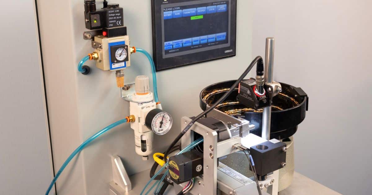
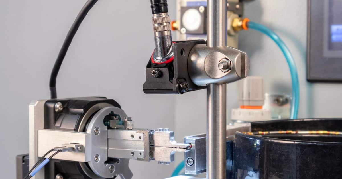
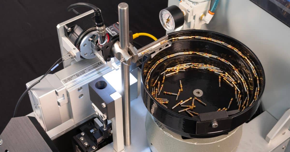
Confirm Terminal and Applicator Compatibility
Many setup delays come from mismatches between terminals, applicators, and the feeding method. Before you run production, verify you have the correct applicator for the terminal series and confirm it remains in good condition.
Pay attention to changes in terminal plating and material. Those variables can affect forming and springback, especially when you run a different supplier lot. If you see intermittent misfeeds or bent terminals early in cycling, fix the underlying alignment or feed issue instead of compensating with pressure or timing changes. Those “workarounds” can hide the real cause and create new defects.
Control Wire Prep Before the Crimper Sees It
Crimp quality depends on consistent input. If the payoff, straightener, or cutter introduces variability, the automatic crimper will struggle no matter how carefully you tune it.
Stabilize wire tension so the conductor does not creep during stripping and transfer. Verify the cut end stays square instead of angled or mashed. Confirm the strip process avoids nicking conductor strands, since strand damage can reduce pull strength and distort the crimp. If your build includes downstream bonding, sealing, or overmolding, treat surface preparation as part of the overall workflow.
Set Strip Length and Insertion Depth for the Terminal Design
Strip length errors create predictable failure modes. Too short can trap insulation in the conductor crimp or reduce the conductor contact area. Too long can leave exposed strands outside the crimp barrel, increase the risk of shorts, and interfere with housing insertion.
Match strip length to the terminal’s conductor barrel depth and insulation support design. Then, verify the insertion depth stays consistent cycle to cycle. When insertion depth drifts, you can see inconsistent conductor compaction even if the crimp height looks correct.
Dial In Crimp Height with a Repeatable Method
Crimp height remains one of the most useful controls because it correlates strongly with mechanical and electrical performance with correct application. The most common mistake is treating crimp height as a single knob instead of a controlled outcome that terminals, wire, tooling condition, and press parameters influence.
Start with the terminal manufacturer’s recommended range when available. Run a short sample set at a steady speed. Measure crimp height the same way every time using the same tool and technique. Adjust in small increments and re-check until you land in the middle of your acceptable window.
After you hit the target, inspect the conductor crimp and insulation support. A crimp can measure “right” and still fail if the conductor wings cut strands, fold strands, or leave voids that reduce contact quality. The insulation support should secure the jacket without crushing it or deforming it in a way that affects downstream fit.
Validate Pull Strength and Failure Mode
Pull testing confirms the setup produces robust terminations, but the failure mode typically tells you more than the peak force. A strand break near the crimp can indicate strand damage from stripping or excessive compression. A terminal pull-off can indicate under-crimp or misformed conductor wings.
During validation, test enough samples to see consistency instead of relying on a single good result. If results vary widely, look upstream at strip consistency, wire tension, and terminal presentation before you assume the crimper needs more parameter changes.
Stabilize Feeding and Positioning Before Fine-Tuning
Teams sometimes tune crimp height or force while the feeding system still produces occasional mispositioned terminals or inconsistent wire insertion. That order makes setup harder and increases the risk of chasing defects.
First, stabilize the terminal feed and presentation. Confirm the system positions the terminal consistently and seats the wire to the correct depth every cycle. Then check for debris control. Cutoff and strip debris can accumulate and change positioning over time, which shows up as intermittent defects that seem random.
Build a First-Article Routine Operators Can Repeat
Another useful tip for a successful automatic wire crimping setup is to build a repeatable process for all shift operators. A setup that depends on tribal knowledge may hold on one shift and fail on the next. Write the routine in the order operators work. Specify the sample count, what to measure, which tools to use, and what results trigger an adjustment.
Also, define what happens when checks drift. Specify who reviews results, allowable adjustments, and when the team should pause the line and request professional service support.
Reduce Changeover Risk with Better Staging
Automatic equipment can make changeovers look simple because recipes load quickly. In practice, physical tooling and feeding changes drive most of the time and most of the risk.
Stage the applicator, terminals, wire, and guides before the change starts. Verify part numbers and revision levels so you do not waste time diagnosing issues from incorrect components.
If you run high-mix jobs, dedicating applicators to the most frequent terminals can reduce tool swaps and protect setup stability. After the changeover, run the same validation sequence every time. Even when you return to a familiar part, lot variation, ambient conditions, and tooling wear can shift results enough to matter.
Treat Preventive Maintenance as Process Control
Consistent crimps require consistent mechanics. Wear in feed mechanisms, loose fasteners, contaminated guides, or aging tooling surfaces can show up as quality drift long before a hard stop.
Build maintenance around practical production demands. When possible, tie checks to cycle counts rather than calendar time. Watch for early indicators such as increasing crimp height variation, rising misfeeds, and climbing scrap rates. When those trends appear, address the mechanical cause rather than compensating through more aggressive settings.
Troubleshoot By Symptom, Not Guesswork
When results look wrong, categorize the symptom before you adjust anything. Crimp geometry problems usually point to applicator alignment, crimp height, terminal selection, or tooling condition. Insertion depth variation typically points to wire handling, strip consistency, transfer timing, or inconsistent wire tension. Intermittent defects frequently point to feed instability or debris buildup.
Capture What You Learn for Faster Next Runs
The fastest way to reduce future changeovers is to document what worked. After you stabilize a job, record the final crimp height, strip length, sample results, machine speed, and any observable sensitivities. Clearly note any special adjustments for particular wire lots or terminal batches, so the next setup starts closer to the target.
Conclusion
Setting up an automatic wire crimper comes from controlling inputs, stabilizing mechanical motion, and validating outputs against clear criteria. When you build repeatability into the setup process, you get more uptime, less scrap, and more consistent results across operators and shifts.