

Common Integration Considerations for Laser Marking
Laser marking can support traceability, product identification, quality control, and production efficiency across many manufacturing environments. However, the performance of a marking system depends on more than the laser itself. Teams must understand the material, production flow, safety requirements, software needs, and validation process before they add a system to the line.
A well-planned integration helps manufacturers get reliable marks without creating bottlenecks or unnecessary handling steps. It also helps engineering, production, and quality teams agree on what the mark needs to accomplish before they define the equipment requirements. The most effective integration plan starts by identifying where marking belongs in the workflow: as a stand-alone operation, as part of a cut-and-strip process, or directly within continuous extrusion or spool-to-spool production. Below, we’ll outline the common integration considerations for laser marking.
Understanding the Material and Marking Surface
Every integration starts with the material. A marking process that works well on one substrate may need different settings, handling, or validation on another. Plastics, coated parts, wires, cables, medical components, and industrial products can all respond differently depending on their surface chemistry, additives, shape, color, and production environment.
Material compatibility affects contrast, readability, permanence, and throughput. For example, a mark must remain clear without interfering with the part’s function or creating downstream quality concerns. Engineering teams should confirm how the substrate responds under realistic conditions, including the same surface condition, coating, and production speed in normal manufacturing.
Confirming Mark Requirements
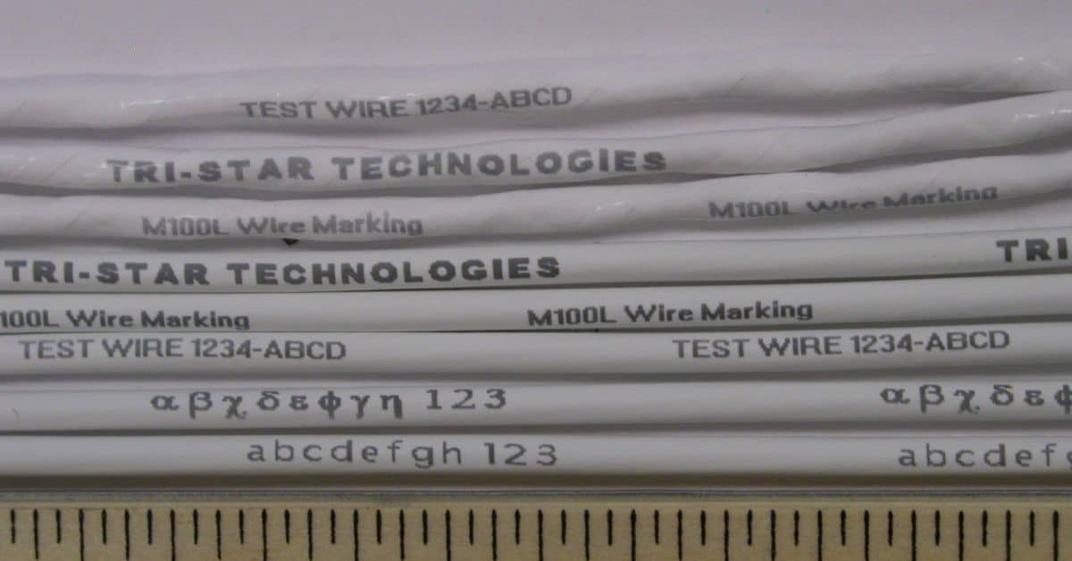
A successful mark starts with a clear definition of what the mark must include. The system may need to apply serial numbers, lot codes, barcodes, logos, symbols, part numbers, or orientation marks. Each format creates different requirements for character size, spacing, scanner movement, and readability.
Teams should also define how operators, scanners, inspection systems, or downstream users will read the mark. A code that looks acceptable during a sample run may not work well if a camera must verify it at production speed. The integration process should connect the mark format to the actual inspection method.
Evaluating Part Geometry
Part shape has a direct impact on mark consistency. Flat surfaces generally simplify alignment, while curved, narrow, flexible, or irregular surfaces require more careful positioning. Small-diameter wire, tubing, and rounded components can make focus, orientation, and character size more important.
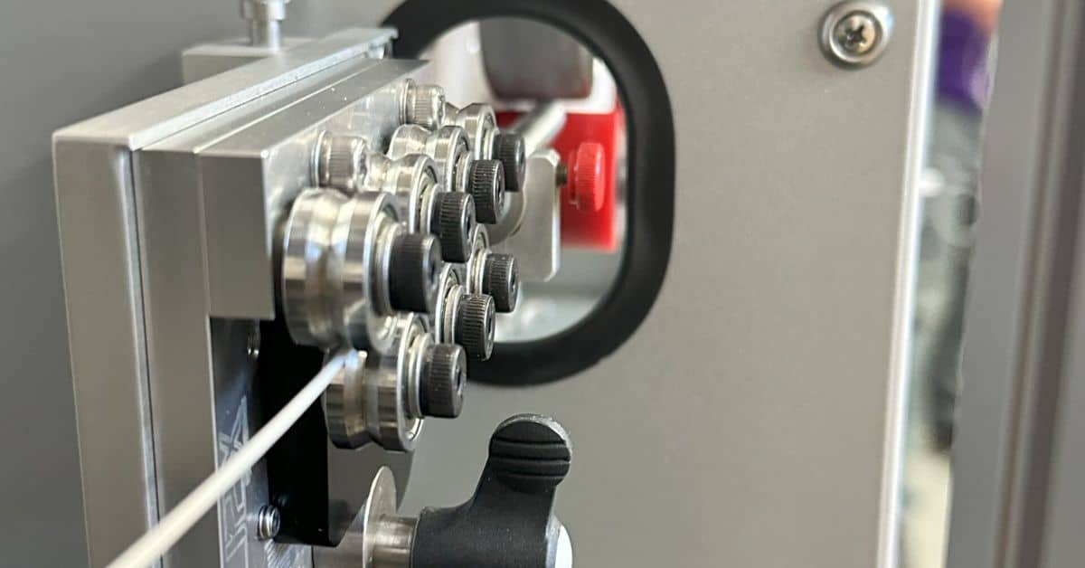
The system must present the surface to the laser in a repeatable way. If parts shift, twist, vibrate, or move through the marking zone inconsistently, mark placement can vary. This becomes especially important in wire, cable, tubing, and filament applications because the material may move continuously through the marking area rather than sit in a fixed nest or fixture. Fixtures, guides, rollers, conveyors, and automated handling systems all help control that presentation.
Matching the System to Production Flow
Another common integration consideration for laser marking is matching the system to the workflow. Some manufacturers need a stand-alone system for batch marking, low-volume jobs, or flexible work cells. Others need in-line marking that keeps pace with continuous manufacturing, wire processing, or automated assembly.
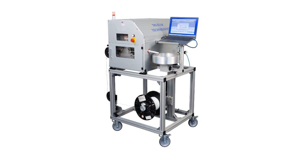
This is where system configuration becomes a practical production decision. For stand-alone workflows, systems such as Tri-Star Technologie’s M100LFGTTA can support controlled marking outside the main production line, giving teams flexibility for batch work, part-specific jobs, and applications that require separate operator review. For extrusion, continuous wire production, and spool-to-spool processing, the M100LFGTTA-METEOR supports in-line integration, where synchronization, material movement, and consistent mark spacing become central to the process.
Stand-Alone Marking Applications
Stand-alone marking can make sense when manufacturers need a controlled marking station that does not have to run directly inside the main production line. This type of setup can support smaller batches, varied part numbers, development work, repair operations, or production environments where operators need more direct control over loading, positioning, and inspection.
In these applications, integration planning should focus on fixture design, operator access, job setup, part presentation, and inspection workflow. The marking system still needs to fit the larger production process, but it may not need the same encoder synchronization, line-speed coordination, or continuous material handling an in-line system requires.
In-Line Extrusion and Spool-To-Spool Marking
In-line marking can reduce handling because the system applies identification as part of the production flow. This approach can improve consistency when the process already includes controlled motion, encoder feedback, or automated part presentation. It can also support traceability earlier in the manufacturing sequence.
Extrusion and spool-to-spool applications create a different set of integration requirements. The system must mark while material moves continuously, so teams must account for line speed, repeat spacing, encoder feedback, tension control, material guidance, and focus stability. In this type of workflow, the M100LFGTTA-METEOR can serve as an integration point within the line rather than a separate secondary operation.
Throughput and Cycle Time
Throughput planning should include more than the speed of the laser. The full cycle includes part loading, positioning, marking, verification, unloading, data transfer, and any operator interaction. A fast mark still creates a bottleneck if the handling process cannot keep up.
Manufacturers should test the complete cycle under realistic conditions. This includes expected line speeds, part spacing, code complexity, and inspection requirements. For stand-alone systems, that means evaluating the time necessary to load and unload each part or batch. For in-line extrusion or spool-to-spool systems, it means confirming that mark placement, spacing, and readability remain consistent as the material moves through ramp-up, steady-state production, and speed changes.
Workflow-Specific Data Needs
Data needs may change depending on how the system fits into production. A stand-alone marking station may rely on stored recipes, operator-selected jobs, imported files, or manual part confirmation before marking begins. This setup places more emphasis on clear job selection, operator prompts, and verification before the system applies the mark.
An in-line or spool-to-spool system may need tighter communication with upstream controls, encoders, material handling equipment, and production software. In those environments, the marking system must receive the right data while staying synchronized with moving material. That makes data flow, signal timing, and line communication part of the integration plan rather than afterthoughts.
Verification and Quality Control
Inspection should be part of the integration plan from the start. Some teams verify marks visually, while others use machine vision, barcode readers, or documented sampling methods. The inspection method should match the risk level, regulatory environment, and traceability requirements of the product.
Quality teams should define acceptable contrast, placement tolerance, code readability, and permanence before production begins. They should also decide how to document results during qualification and routine production. This avoids confusion when a mark looks acceptable but fails a scanner, customer specification, or internal requirement.
Addressing Safety and Facility Requirements
Laser marking equipment needs appropriate safety controls. This is why all Tri-Star Technologies’ laser marking systems are rated Class 1 thanks to safety measures like enclosed marking areas, interlocks, laser safety glass, exhaust management, warning labels, operator training, and controlled access. As a result, they are rated for shop floor operation without additional required PPE during normal use.
Facility planning should also account for power, footprint, ventilation, environmental conditions, and access for trained service personnel. Teams should avoid treating safety and installation as late-stage details. These requirements can affect where the system fits, how operators interact with it, and how the process runs day to day.
Operator Access and Equipment Placement
Equipment placement should reflect the type of workflow the system supports. A stand-alone system needs practical access for loading, unloading, setup, and inspection. Operators should be able to select jobs, confirm part position, and monitor the process without awkward movement or unnecessary handling.
An in-line system needs to fit into an existing production path without disrupting upstream or downstream equipment. In extrusion or spool-to-spool applications, teams should plan for material entry and exit, line clearance, service access, cable routing, and the physical relationship between the marking system, guides, encoders, and take-up or payoff equipment.
Environmental Conditions
The marking environment can affect consistency. Dust, debris, vibration, temperature changes, and unstable part handling can all interfere with the process. The system should fit the realities of the production floor, cleanroom, lab, or manufacturing cell where it will operate.
Manufacturers should also consider how the product reaches the marking area. Parts may arrive with surface contamination, static, coatings, or handling residue that affects mark appearance. In continuous wire and cable workflows, upstream process stability can have a direct effect on downstream mark consistency because movement, surface condition, and material presentation all occur in real time. A stable environment and consistent upstream process help the marking system deliver repeatable results.
Validating By Integration Type
Validation should reflect the selected integration point. A stand-alone application may require testing across different fixtures, part orientations, operator workflows, and job recipes. The goal is to confirm that the process stays repeatable when operators move between part types or production batches.
An in-line extrusion or spool-to-spool application should include testing at expected line speeds, mark intervals, material tensions, and production transitions. Teams should confirm that the system maintains mark spacing, placement, and readability while the material is moving, not only during static sample tests.
Documenting Parameters and Changeovers
Teams should document the settings that produce acceptable results, including power, speed, focus, mark position, character size, line spacing, fixture setup, material guidance, and inspection criteria. Strong documentation helps operators repeat the process and helps quality teams troubleshoot changes.
Changeover planning should also reflect the workflow. A stand-alone system may require recipe selection, fixture changes, or part-specific setup checks. An in-line system may require coordination with line settings, material diameter, encoder calibration, and mark spacing requirements. Clear documentation ties the marking process to proven conditions as production needs change.
Conclusion
Laser marking integration works best when teams treat it as a production process, not a single equipment purchase. Material compatibility, part geometry, data flow, safety requirements, inspection methods, and operator workflow all shape the result. When manufacturers address these considerations early, they can improve mark consistency, reduce handling issues, and support stronger traceability.
The right integration path depends on where marking belongs in the workflow. Some applications call for a stand-alone system such as the M100LFGTTA, while others require in-line coordination through systems such as the M100LFGTTA-METEOR for extrusion or spool-to-spool production. If your team needs help evaluating a laser marking application, Tri-Star Technologies can review your production requirements and help identify whether a stand-alone, in-line, or continuous processing configuration fits your process.